

Reverse engineering teams often work with legacy components, physical samples, repaired parts, or complex surfaces for which complete CAD data is unavailable. Capturing reliable three-dimensional information is therefore an important first step. A handheld 3D scanner can convert physical geometry into digital data without requiring extensive fixed equipment, helping engineering teams accelerate data capture, modeling, inspection, and product development.
Start with Flexible On-Site 3D Data Capture
A reverse engineering workflow begins with collecting the geometry of the target component. Traditional manual measurement can require numerous individual measurements, reference points, and repeated setup operations, particularly when the workpiece contains curved or irregular surfaces.
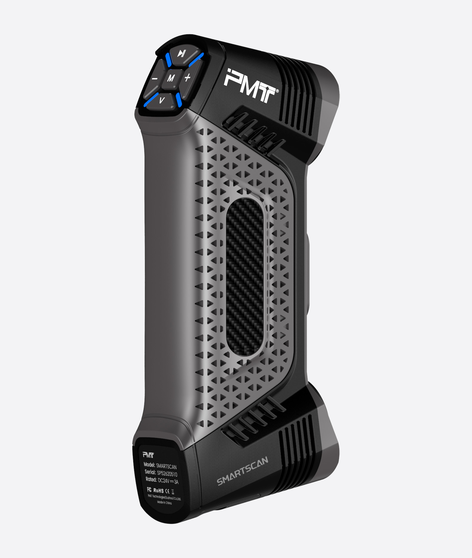
A handheld laser 3D scanner approaches the task differently by capturing surface geometry as dense three-dimensional data. PMT’s SMARTSCAN is designed as a lightweight, non-contact measurement solution for industrial environments, allowing one operator to perform on-site scanning without fixed installation.
This portability is useful when components are large, difficult to move, or already installed in a production environment. Reverse engineering teams can bring the measurement equipment to the part instead of reorganizing the workplace around the measurement system.
Select the Appropriate Laser Mode for the Geometry
Reverse engineering projects rarely involve only simple flat surfaces. A single component may include broad surfaces, narrow grooves, small features, deep holes, and internal cavities. The scanning workflow therefore needs to accommodate different levels of geometric detail.
PMT SMARTSCAN supports three laser modes: 51 crossed blue laser lines, seven parallel blue laser lines, and a single blue laser line. The crossed-line mode supports rapid coverage, while the parallel-line mode is designed for capturing finer surface features. The single-line mode can address deeper holes and internal areas.
The published specifications list a maximum scanning rate of 5,508,000 measurements per second, a maximum scanning field of 700 mm × 600 mm, a 300 mm reference working distance, and a 550 mm scanning depth of field. These specifications provide reverse engineering teams with practical parameters for planning their scanning approach.
Build a Complete Digital Representation
Once scanning begins, the objective is not simply to collect isolated measurements. The captured data needs to form a coherent representation of the physical component that can support subsequent engineering work.
SMARTSCAN works with PMT’s SkyForm software, which integrates scanning acquisition with functions such as real-time scanning, mesh optimization, automatic noise removal, and hole filling. The handheld 3D scanner can output formats including STL, OBJ, PLY, ASC, IGS, TXT, and MKPTS, providing options for subsequent processing and engineering workflows.
For reverse engineering teams, this data interoperability can make the transition from physical part to digital model more manageable. Depending on the project, engineers can use the resulting point-cloud or mesh information as the foundation for reconstruction, dimensional analysis, design modification, or further CAD development.
Move from Scanning to Engineering Analysis
Data acquisition is only one stage of reverse engineering. The real business value comes when captured geometry can support decisions about design, manufacturing, repair, or product improvement.
PMT describes reverse engineering applications for SMARTSCAN that include obtaining three-dimensional data from complex workpieces, generating point-cloud or mesh models, reconstructing surfaces, and supporting product redesign. This makes scanning relevant to teams dealing with parts that lack drawings or require further development.
The workflow can also connect scanning with inspection. PMT states that scan data can be imported into its PMT INSPECT 3D measurement software for geometric tolerance evaluation, creating a path from data acquisition to dimensional assessment.
Combine Reverse Engineering with Quality Verification
A reverse engineering project may need to answer more than “What does this part look like?” Teams may also need to determine whether a manufactured, repaired, or worn component still matches its intended geometry.
SMARTSCAN supports CAD comparison, dimensional inspection, and assembly verification according to PMT’s published application information. Scanned data can therefore be compared with existing design information to identify areas of deviation rather than relying exclusively on manual measurements.
This approach can be particularly useful when reverse engineering and quality assurance overlap. For example, an engineering team can digitize an existing component, analyze its geometry, and subsequently use the same data to investigate dimensional differences or support product improvements.
Connect Scanning with Larger Measurement Systems
Some projects require more than a standalone scanner. Large components, repeated inspections, or automated production environments may benefit from combining multiple measurement technologies.
PMT SMARTSCAN can be paired with industrial robots and photogrammetry systems. PMT describes this interoperability as a way to support complex measurement requirements and enable automated inspection workflows. Its global photogrammetry approach can also help address the overall accuracy requirements of larger workpieces.
For engineering organizations, this creates an opportunity to develop a scalable measurement process. A handheld 3D scanner can serve individual reverse engineering tasks while integration with other equipment can support larger or more automated inspection programs.
Make Portability Part of the Workflow
The physical design of the equipment also affects how efficiently a reverse engineering team can work. SMARTSCAN weighs 530 g without the battery and has a stated power consumption of 4.8 W. Its operating temperature range is -10°C to 40°C, while the recommended minimum computer configuration includes Windows 10 or later, an i7-13700H-class processor, an NVIDIA RTX 4060-class graphics card, 8 GB of graphics memory, and at least 64 GB of RAM.
These specifications help teams evaluate not only scanner performance but also the supporting infrastructure required for deployment.
Creating a More Efficient Reverse Engineering Pipeline
A well-designed handheld laser 3D scanner workflow can connect physical data capture with digital modeling, inspection, and engineering analysis. PMT SMARTSCAN combines multiple blue-laser scanning modes, lightweight operation, SkyForm processing, and interoperability with PMT INSPECT and other measurement technologies.
For business engineering teams, the main consideration is how these capabilities fit into the existing reverse engineering process. When portable scanning, data processing, CAD comparison, and inspection are connected effectively, organizations can reduce manual measurement work and create a more consistent path from physical components to actionable digital engineering data.
